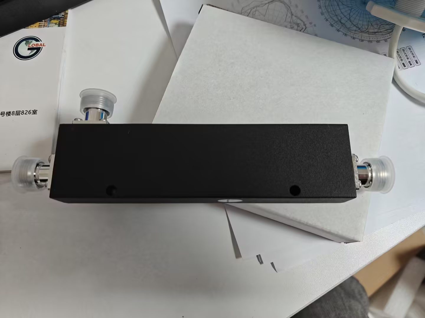
GL-130 series directional coupler for 136–174MHz VHF in-building systems. 200W average power, low VSWR, high isolation, N-female connectors. Available in 5/6/7/10/15/20dB coupling options.
Home > Product > Related Products > GL-130 Series Directional Coupler (N-Female)
GL-130 Series - Directional Coupler for 136–174MHz networks, available in 5/6/7/10/15/20dB coupling options with N-female Connectors.
GL-130 series directional couplers are designed for indoor in-building solutions where stable RF sampling and signal distribution are required. The series covers 136–174MHz, supports up to 200W average power, features low VSWR (≤ 1.25), and provides high isolation performance across multiple coupling values.
Key Features | |
Wide Band 136–174MHz Covers 136–174MHz for VHF in-building and coverage enhancement systems. | Multiple Coupling Options Choose 5/6/7/10/15/20dB models to match monitoring level and system design. |
Low VSWR & Insertion Loss VSWR ≤ 1.25 with low insertion loss across the series to help protect link budget. | High Isolation High isolation performance (up to ≥ 38dB depending on coupling value) for cleaner sampling. |
200W Average Power Supports up to 200W average power handling for demanding indoor RF distribution. | Indoor IP60 Housing Indoor-rated enclosure and stable performance for in-building solutions (IP60). |
| System | Parameter | Specification |
|---|---|---|
| RF Performance | Frequency Range | 136–174MHz |
| Coupling (dB) | 5 / 6 / 7 / 10 / 15 / 20 (by model) | |
| Insertion Loss (dB) | ≤2.2 (5dB) / ≤1.9 (6dB) / ≤1.40 (7dB) / ≤1.0 (10dB) / ≤0.4 (15dB) / ≤0.3 (20dB) | |
| Coupling Accuracy (dB) | ±1.2 (5/6/7/10dB) / ±1.3 (15dB) / ±1.4 (20dB) | |
| Isolation (dB) | ≥24 (5dB) / ≥25 (6dB) / ≥26 (7dB) / ≥28 (10dB) / ≥34 (15dB) / ≥38 (20dB) | |
| Interface & Power | VSWR | ≤ 1.25 |
| Power Handling | 200W (average) | |
| Impedance | 50Ω | |
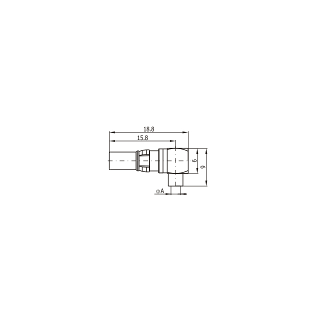
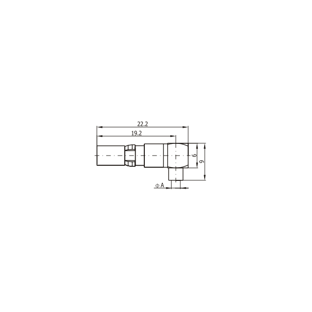
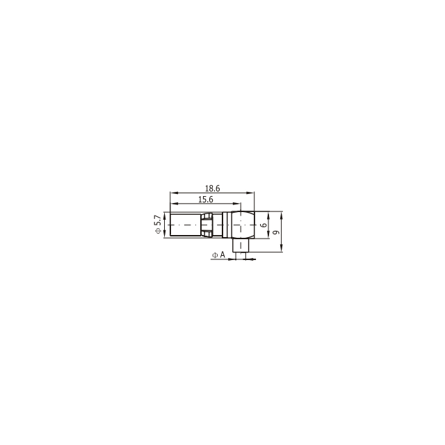
| Connector | N-female | |
| Model Options | GL-130-05-NF / GL-130-06-NF / GL-130-07-NF / GL-130-10-NF / GL-130-15-NF / GL-130-20-NF | |
| Mechanical | Dimensions (L×W×H) | 179 × 55 × 19mm |
| Net Weight | 0.28kg | |
| Color | Black | |
| Mounting | Mount via installation hole on coupler body (see installation instructions) | |
| Environmental | Operating Temperature | -30℃ ~ +65℃ |
| Relative Humidity | 5% ~ 95% | |
| Ingress Protection | Indoor IP60 | |
| Grounding | Ensure proper grounding during installation and use | |
| Compliance | Environmental Compliance | Not specified in provided documents |
In-building solutions (VHF 136–174MHz) requiring signal sampling or distribution
Distributed Antenna Systems (DAS) and indoor coverage enhancement networks
RF test points for measurement, commissioning, and maintenance
Installations requiring N-female interfaces and 200W average power handling
|
|
Request Quote Request Sample Download PDF
MOQ 50 units | Lead Time 1-2 weeks | Warranty 1 year |
| Model | Frequency | Input VSWR | Output VSWR | Insertion Loss | Coupling Accuracy | Isolation | Result |
|---|---|---|---|---|---|---|---|
| GL-130-10 NF 10dB Directional Coupler | 136–174MHz | 1.17 (≤1.25) | 1.18 (≤1.25) | 0.68 dB (≤1.0) | 9.2–10.9 dB (10±1.2) | 31 dB (≥28) | PASS |
| GL-130-15 NF 15dB Directional Coupler | 136–174MHz | 1.15 (≤1.25) | 1.17 (≤1.25) | 0.26 dB (≤0.4) | 14.3–15.8 dB (15±1.3) | 36 dB (≥34) | PASS |
| ⚠️ | Application Precautions
|
Mounting Procedure |
| 1.Use the installation hole located on the cavity coupler body2.Determine installation position on mounting bracket; drill holes at specified location and secure expansion bolt sleeves3.Pass screw through cavity coupler (through installation holes), fix onto expansion bolt sleeve, and tighten firmly using Phillips screwdriver4.Connect signal from source port to Input Port; connect coupling port and Output Port to the feeder |
Port 1 Input Port Signal Source → | Coupling Port Coupled Output Sampling/Monitoring | Port 2 Output Port → To Antenna/Load |
| Installation Manual (PDF) | Complete installation instructions with diagrams for cavity coupler mounting and port configuration. | Download |
| Test Report Template (Excel) | Factory test data format including VSWR, Insertion Loss, Isolation measurements for quality verification. | Request |
The GL-130 series provides 5dB, 6dB, 7dB, 10dB, 15dB, and 20dB coupling options. Models include GL-130-05-NF, GL-130-06-NF, GL-130-07-NF, GL-130-10-NF, GL-130-15-NF, and GL-130-20-NF.
The operating frequency range is 136–174MHz. The rated power is 200W (average).
The coupler uses N-female connectors and has a 50Ω impedance.
Follow these key points: keep the unit dry during storage and transport; clearly distinguish Input/Output ports (do not use the Output port as Input); ensure proper grounding; check and tighten connectors; and do not operate above the rated power to avoid performance degradation.
Contact: Diana Xie
Phone: 86-15815571536
E-mail: sales@global-antenna.com
Whatsapp:8615815571536
Add: Room826, Floor 8,BLDG 13, University Science Park(East), Zhengzhou City, P.R.Henan, China.Zip Code: 450000
")
")