
GL-SP001 is a 2-way indoor power splitter for 136–174MHz with N-female connectors, low insertion loss ≤0.4dB, VSWR ≤1.25, ≥20dB isolation, and 50W power handling for in-building RF distribution.
Home > Product > Anterna related products > GL-SP001
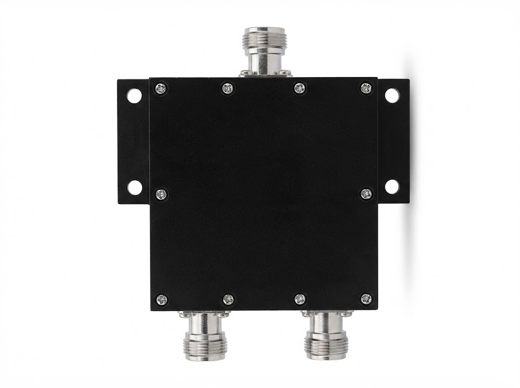
GL-SP001 - 2-way indoor power splitter for 136–174MHz signal distribution with N-female Connectors.
Designed for in-building RF distribution, this 2-way power splitter covers 136–174MHz and provides a balanced 3.0dB split with low insertion loss (≤0.4dB). It offers high isolation (≥20dB), excellent matching (VSWR ≤1.25), 50Ω impedance, and supports up to 50W total input power. The compact unit uses N-female connectors and is intended for indoor deployment in DAS and signal distribution networks.
Key Features | |
Wide Frequency Band (136–174MHz) Supports VHF operation across 136–174MHz for consistent coverage in signal distribution systems. | Low VSWR & Low Insertion Loss VSWR ≤1.25 with insertion loss ≤0.4dB to help maintain link quality and reduce power waste. |
Balanced 2-Way Split 1 input / 2 outputs with typical split loss of 3.0dB for even power division. | High Port-to-Port Isolation Isolation ≥20dB to minimize interaction between output branches. |
50W Power Handling Rated for up to 50W total input power for indoor RF infrastructure applications. | 50Ω, N-Female Interface Standard 50Ω impedance with N-female connectors for easy integration with common coaxial components. |
| System | Parameter | Specification |
|---|---|---|
| Electrical | Frequency Range | 136–174 MHz |
| Input / Output Ports | 1 input / 2 outputs | |
| Split Loss | 3.0 dB | |
| Insertion Loss (IL) | ≤ 0.4 dB | |
| Isolation | ≥ 20 dB | |
| VSWR | ≤ 1.25 | |
| Total Input Power | 50 W | |
| Impedance | 50 Ω | |
| Connector | N-female | |
| Mechanical | Color | Black-plated |
| Application | Indoor | |
| Environmental | Operating Temperature | -35℃ ~ +75℃ |
Indoor distributed antenna systems (DAS) and in-building coverage networks (VHF 136–174MHz).
RF signal splitting for repeaters, base stations, and feeder distribution inside equipment rooms.
VHF radio communication infrastructure requiring low loss and stable matching.
Any indoor RF system needing a compact 2-way splitter with N-female interfaces and 50Ω impedance.
! Important Safety Notes
• Dry storage required
• Protect from moisture
• Check connectors
• Do not reverse use
• Proper grounding
• Max 50W power
| Installation Procedure | |
| STEP 1 | Position & Mark Determine mounting position on bracket according to hole locations. |
| STEP 2 | Drill & Anchor Drill holes and secure expansion anchor sleeves. |
| STEP 3 | Mount Splitter Insert screws, fix into anchor sleeves, tighten with screwdriver. |
| STEP 4 | Make Connections Connect source to input, outputs 1 & 2 to antenna feeders. |
Installation Reference Diagram Note: Diagram shows 4-way splitter for reference. GL-SP001 (2-way) follows the same mounting principle. |
| Professional Installation Recommended For optimal performance and safety, installation by qualified RF technicians is advised. Always verify system compatibility and conduct post-installation testing. |
|
|
Request Quote Request Sample Download PDF
MOQ 50 units | Lead Time 1-2 weeks | Warranty 1 year |
Split loss describes the theoretical division loss when one input is split into two outputs. For GL-SP001, the specified split loss is 3.0dB, meaning the input power is evenly divided between the two output ports (excluding additional losses).
Insertion loss (IL) is the extra loss introduced by the component beyond the ideal split. GL-SP001 specifies IL ≤ 0.4dB, helping keep total path loss low in indoor RF distribution.
GL-SP001 operates across 136–174MHz and uses N-female connectors with 50Ω impedance for compatibility with common coaxial RF systems.
GL-SP001 is intended for indoor use in in-building solutions such as DAS and RF distribution networks. It supports up to 50W total input power and operates from -35℃ to +75℃.
Contact: Diana Xie
Phone: 86-15815571536
E-mail: sales@global-antenna.com
Whatsapp:8615815571536
Add: Room826, Floor 8,BLDG 13, University Science Park(East), Zhengzhou City, P.R.Henan, China.Zip Code: 450000